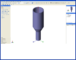
Dual mode horn antenna
 
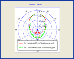
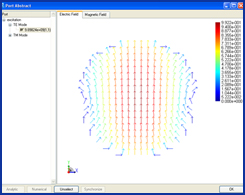
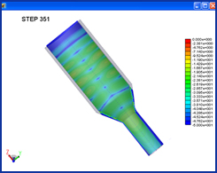
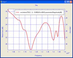
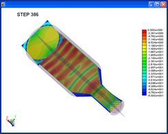
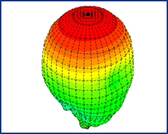
A dual mode circular horn antenna has a very low side lob in its far field pattern. A TE11 mode at the lower guide is used to excite the antenna, and the combination of TE10 and TM11 modes are formed at the aperture of the upper guide to generate a low lobe far field pattern.
 
The basic design procedure in the simulation:
Draw an upper cylinder
Draw a lower cylinder
Select the two inner surfaces (the bottom of the upper cylinder and the top of the lower cylinder) and use the “Loft” option to generate the transit
Select the top and bottom surfaces and use the “Shelling” option to generate the horn
Draw a circle at the bottom of lower guide, and select the TE10 mode as excitation
Set the domain size and boundary
Generate the adaptive mesh
Set the far field output parameters
Specify the convergence criterion
Simulate the project using a single PC
The basic settings in the simulation:
Option
Setting
Description
BoundaryPML truncates all six walls

Due to the symmetric feature, you can simulate only the half or quarter of the original problem

Excitation

TE11 mode backed by match load

The match load to simulate the infinitely long feed guide
MeshThe minimum cell  size equals to the half of the guide thicknessThe half guide thickness to ensure no power leaking through the guide wall
OutputReturn loss, mode impedance, far field pattern and field distribution inside the guideTo view the field behavior through the guide 
SimulationA multiple core PCA single PC can simulate this problem
 

Dual Mode Horn Antenna


Directivity Patterns at 12GHz

TE10 Mode Pattern


Field Distribution Inside Horn (1)

Return Loss of TE10 Mode


Field Distribution InsideHorn (2)

3-D Far Field Pattern at 12GHz