Waveguide filter
 
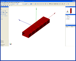
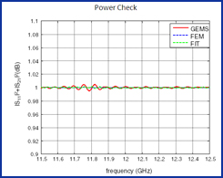
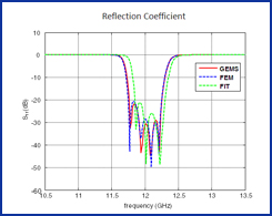
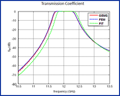
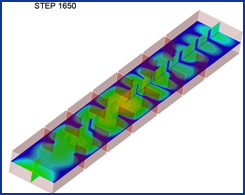
A waveguide filer that is a high-Q system is simulated by using GEMS. The TE10 mode is used to excite the filter. It usually takes longer time than the regular system due to high-Q property.
 
The basic design procedure in the simulation:
Import the filter model in SAT format into GEMS, which is the solid in the original file
Select all the surfaces using the “Surface Selection” option in the Tool Box -> Geometry box.
Unselect two end surfaces
Press and hold “Ctrl +c” and then “Ctrl + v” to copy and paste the surfaces
Assign the pasted surfaces as PEC material
Group them as a single object
Delete the original model
Draw two rectangles at the two ports and specify one of them as excitation and the other one as output
Use TE10 as the excitation and output mode
Specify the domain size and boundary. The two ports are truncated by PML and other four walls are truncated by PEC boundary
Generate the adaptive mesh
Specify the convergence criterion
Simulate the project using a single PC or cluster
The basic settings in the simulation:
Option
Setting
Description
BoundaryPML and PEC boundary

PML at the two end sides
PEC truncated other four sides

Excitation

TE10 mode ports

The mode port can touch the PML boundary
MeshNon-uniformThe mesh should pass the key edges inside the guide
OutputS-parameters, field distribution inside filter and power check 
SimulationA multiple core PC 
 

Waveguide Filter Model


Power Check

Reflection Coefficient


Field Distribution Along
the Axis

Transmission Coefficient


Field Distribution Inside
Filter

3-D Field Distribution
Inside Filter