
|
| Microwave component |
| |
| A three-port microwave component filled with metamaterial is simulated by using GEMS. One port serves as an excitation, and other two ports are the outputs. GEMS is used to simulate the S-parameters and field distribution inside the component. |
| |
| The basic design procedure in the simulation: |
 | Draw a box and generate a shell using the “Shelling” option | | Assign it to be PEC material | | Add three ports | | Import the metamaterial into the box and assign it to be lossy material | | Draw three rectangles at the three ports and define one of them as the excitation port and other two as the output ports | | Use the TE10 as the excitation mode | | Set the domain size and boundary | | Generate the adaptive mesh | | Specify the convergence criterion | | Simulate the project using a single PC or cluster |
|
| The basic settings in the simulation: |
| Option | Setting | Description | | Boundary | PML truncates three sides that touch the three ports; PEC truncates other three sides | PEC boundary is used due to the closed system. | | Excitation | Mode port | TE10 mode | | Mesh | Non-uniform and conformal mesh | Adaptive mesh | | Output | S-parameters, and time domain field distribution inside the component | It will take long time to get the convergence result due to the high-Q property | | Simulation | A PC or cluster | |
|
| |
Microwave Filter Model | 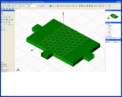 | | | Magnetic Field Pattern of
TE10 Mode | 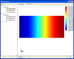 |
| Filled Metamaterial | 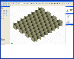 | | | Electric Field Distribution
Inside Filter (1) | 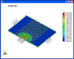 |
| Electric Field Pattern of
TE10 Mode | 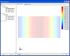 | | | Electric Field Distribution
Inside Filter (2) | 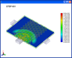 |
|
|
Electric Field Distribution
Inside Filter (3) | Electric Field Distribution
Inside Filter (4) | 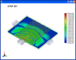 | 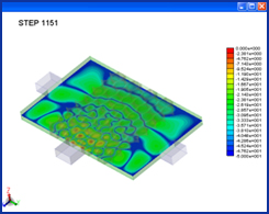 |
|