
|
| MIMO Antenna |
| |
| GEMS is used to simulate the MIMO antenna that includes two PIFA antennas. The antenna is relatively thin compared to its dimensions in the horizontal directions (550:1). GEMS allows you to use a flat domain and achieve the accurate results. The output parameters are MEG, ECC, S-matrix, total active reflection coefficient, and far field patterns. In this showcase, we also compare the simulation result using the large, mediate and small domains in the z-direction. |
| |
| The basic design procedure in the simulation: |
 | Draw the substrate first and then assign the dielectric material to it |  | Draw an “F” shaped structure |  | Draw a ground and assign it to be PEC |  | Draw a via at one end of the PIFA |  | Draw a line between another end of the PIFA and the ground, and assign it as a lumped port. Assign its group ID to be “1” |  | Select the PIFA, probe and lumped port, and click on the Mirror button in the toolbar to generate an image about the symmetric plane. |  | Change the group ID of the imaged lumped port to “2” |  | Check the “Output far field pattern for each excitation” in the far field parameter setting window |  | Specify the domain size and boundary (PML). |  | Generate the adaptive mesh |  | Specify the convergence criterion |  | Simulate the project using a single PC or cluster |
|
| The basic settings in the simulation: |
| Option | Setting | Description | | Boundary | PML truncates six walls | Open space problem | | Excitation | Lumped port | Provide a match load for an open port and excitation | | Mesh | Non-uniform | Adaptive mesh | | Output | MEG, ECC, S matrix, far field patterns | Parameters of MIMO antenna | | Simulation | A multiple core PC or cluster | |
|
| |
Dual PIFA Antenna | 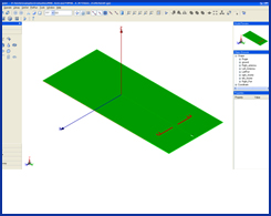 | | | Far Field Patterns | 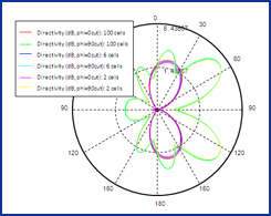 |
| S-Parameters | 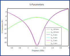 | | | ECC | 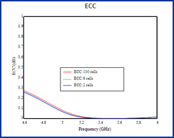 |
| Radiation Efficiency | 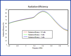 | | | MEG | 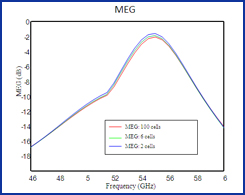 |
|
|
3-D Far Field Pattern | | 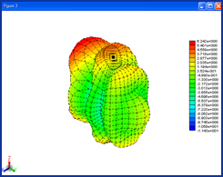 | |
|


